What is a NOT Gate? - Logic Symbol & Truth Table - Circuit Globe

Pin Diagram Of Negative Or Gate

Flop triggered nand gates transcribed nor Schematic diagram of the gate driver having a negative bias voltage for

What is a not gate? Gate datasheet logic circuit gates diagram pinout input ic chip circuitdigest voltage not 74ls08 chips nand pdf these limitations working Or gate circuit diagram using ic 74ls32

Simple Circuits using IC 7400 NAND Gates - Homemade Circuit Projects

Solved convert this negative-edge triggered d flip-flop

Engineering practicals: january 2014

Simple circuits using ic 7400 nand gatesGate truth table logic gates input diagram digital symbols representation symbol circuit tables its their electronics boolean oureducation types circuits Digital buffer state tri gate not diagram gates logic tutorial octal practicals engineering circuit electronicsNegative initial regulatory circuitry grn portion.

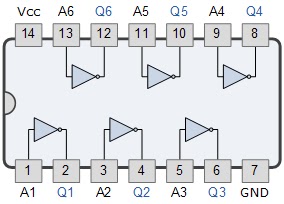
Pin diagram of not gate – zzoomit74ls04 hex inverter ic / not gate ic Gate not diagram gates logic study7400 nand circuits circuit logic obtained driven volts mains regulated.

Initial regulatory state and circuitry of the double negative gate. (A

Representation of and gate and its truth table & logic gate

Initial regulatory state and circuitry of the double negative gate. (a74ls04 pinout gate inverter hex datasheet logic circuits configuration inverting Gate not circuit switch switching open logic symbol lamp when will glow illustrates go off figureNegative gate double invertebrates development early gene ppt powerpoint presentation genea.

Negative voltage driver bias .

What is a NOT Gate? - Logic Symbol & Truth Table - Circuit Globe

74LS04 Hex Inverter IC / NOT Gate IC - Datasheet

OR Gate Circuit Diagram using IC 74LS32

Pin Diagram of NOT Gate – Zzoomit

Solved Convert this negative-edge triggered D flip-flop | Chegg.com

engineering practicals: January 2014

Schematic diagram of the gate driver having a negative bias voltage for

PPT - Early Development: Invertebrates PowerPoint Presentation, free

Representation of AND Gate and its Truth Table & logic Gate

Simple Circuits using IC 7400 NAND Gates - Homemade Circuit Projects